Types of accelerators
Types of accelerators
As mentioned on the previous page, particle accelerators are devices that accelerate charged particles using electromagnetic fields.
Particle accelerators can be split into two fundamental types, electrostatic accelerators and oscillating field accelerators. Electrostatic accelerators, such as the Cockcroft-Walton accelerator and the Van de Graaff accelerator make use of what is known as an electrostatic field. Electrostatic fields are simply electric fields that do not change with time. The main disadvantage of using electrostatic fields is that very large electric fields need to be generated to accelerate particles to experimentally useful energies, which would be difficult and dangerous to maintain. This disadvantage led to the development of the second type of accelerator: the oscillating field accelerator. This type of accelerator requires electric fields that periodically change with time. Clever use of this oscillating electric field has allowed high energy physicists to accelerate particles to extremely high energies, leading to many key discoveries that shape our view of the universe.
Main categories of particle accelerators are detailed below.
- The Cockcroft-Walton and Van de Graaff Accelerators
- The Linear Accelerator (Linac)
The Cockcroft-Walton and Van de Graaff Accelerators
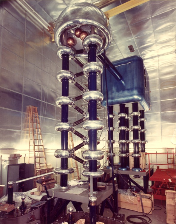
These accelerators are two types of particle accelerators developed in the early 1930’s, the Cockcroft-Walton accelerator was developed by John Cockcroft and Ernest Walton at the Cavendish Laboratory in Cambridge, England, and the Van de Graaff Accelerator was developed by Robert Van de Graaff whilst working as a post-doctorate research assistant at Princeton in the US. Both accelerators simply accelerated charged particles by generating very high voltages. The Cockcroft-Walton accelerator generated a high voltage by creating a complex electrical circuit called a voltage multiplier cascade, which became known as Cockcroft-Walton generator. Using their generator, Cockcroft & Walton were able to generate a voltage of 800kV (800,000V).
|
This voltage then accelerated protons along an 8 foot vacuum tube, where they then collided with a Lithium target achieving the first artificial nuclear disintegration in history. Cockcroft-Walton generators are still used in particle accelerators today for the initial acceleration of particles before they go on to larger accelerators.
Cockcroft-Walton accelerator. Image credit: Brookhaven National Laboratory |
The method of generating a voltage in a Van de Graaff accelerator is much simpler. In fact most people will be familiar with a Van de Graff generator from their school days.
|
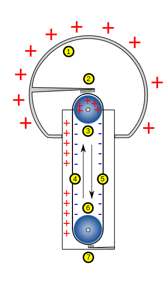
A Van de Graaff accelerator consists of a large metallic sphere (1) at the top of an insulating column. Within the column is a belt made from a conducting material (4 & 5) pulled taught over two pulleys (3 & 6). One of the pulleys is attached to an electric motor driving the belt (6), at either end of the belt is a brush of metallic wires (2 & 7), the lower brush (7) is attached to a voltage source which transfers a charge to the belt via the brush, the belt then carries the charge up (4) to the second brush which will transfer the charge to the large metal sphere known as the electrode. The charge build-up generated in the electrode results in a potential difference between the electrode and the ground.
A diagram of a Van de Graff generator. Image credit: Dake, Wikipedia, Modified: Daniel Potter/TIARA |
A particle can be accelerated using this potential difference, from the electrode, to the ground. A Van de Graaff accelerator is a very big Van de Graaff generator with an accelerator tube contained within it. By 1933 a Van de Graaff accelerator was in operation that could accelerate hydrogen ions to an energy of 0.6MeV (600,000eV).
|
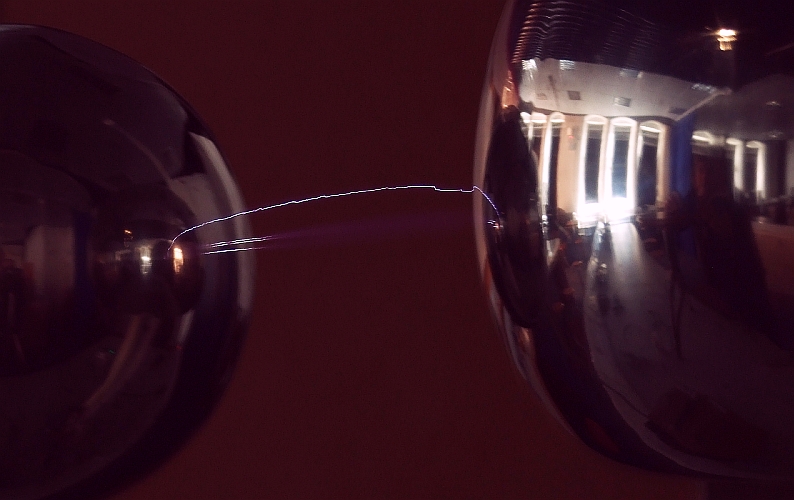
Spark on Van de Graff generator. Image credit: Stuart Anthony |
The Linear Accelerator (Linac)
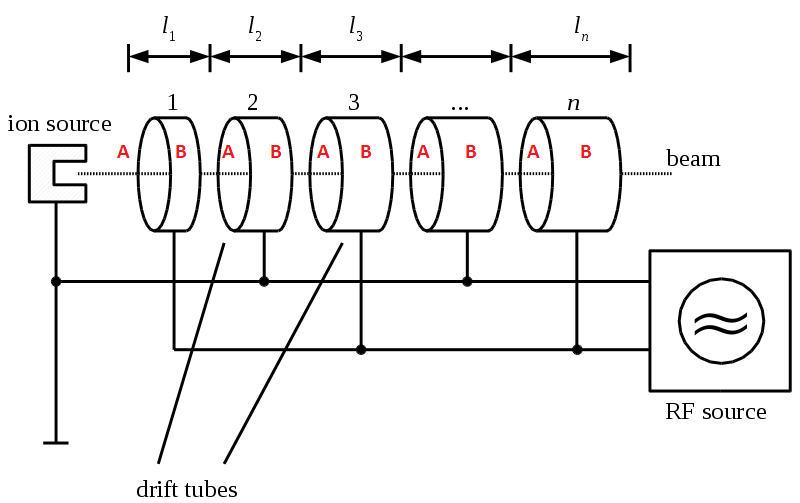
The first development in Linear Accelerators came from Rolf Widerøe in 1927 when he built a linear accelerator using an alternating current (AC) voltage and a series of drift tubes. In an alternating current, the flow of electric charge is periodically reversed, the flow of electric charge can be thought of as a series of peaks and anti-peaks of voltage. A charged particle acted on by an AC voltage would be accelerated from point X to point Y, during a peak, then when the current is reversed would be accelerated back from point Y to point X, during an anti-peak.
|
A schematic of Widerøe’s accelerator. Image credit: Florian Nolz, Wikipedia, Modified: Daniel Potter/TIARA |
In his accelerator, Widerøe used a series of drift tubes to shield the particle being accelerated from the reversed electric field during an anti-peak preventing it from being decelerated (B). The particle then emerges from the drift tube just as the field returns to a peak, where it is further accelerated (A). As the particle gets faster and faster, the drift tubes need to be longer and longer. Indeed the faster the particle moves, the greater distance it covers in the same amount of time. This is one of the limiting factors of linear accelerators, they need to be very long for particles to be accelerated to high energies.
The Stanford Linear Accelerator Centre (SLAC) is the home of the world’s largest Linac which is 2 miles long and capable of accelerating electrons and positrons (the anti-matter equivalent of the electron) to energies of 50GeV (50,000,000,000eV). The advantages of Linacs over other types of accelerators is that they are capable of accelerating larger ions than circular accelerators like those described below, and it is easier to produce high energy electron beams again as they do not use a circular path. Linacs are still widely used today in research and in medicine.
|
|
The Cyclotron
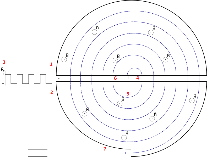
In 1928 Ernest Lawrence of the University of California, inspired by the work of Widerøe, had the idea of utilizing a curved path for a particle accelerator. A magnetic field perpendicular to the plane of motion of an accelerated particle will result in the particle taking a curved path. By studying the simple relationship between the forces acting on the particle, Lawrence realised that the increase in the radius of the path taken by the particle is compensated for by the increased velocity of the particle if the magnetic field, the charge of the particle and the particles mass remain constant. With this in mind, he built what became known as a Cyclotron. It consisted of two hollow D-shaped electrodes (1 & 2) alternatively charged to a voltage by an oscillator (3). The electrodes were separated by a small gap. When one of the electrodes is charged, a particle is accelerated across the gap into the other (4), where, under the influence of a magnetic field, it moves in a semi-circular path back to the surface of the electrode (5). Just as the voltage has charged the other electrode, the particle is again accelerated across the gap (6). As the speed of the particle increases, the radius of the semi-circular motion of the particle increases until the particles are eventually focused out of the Cyclotron as a high energy beam (7).
|
A basic diagram of a Cyclotron [note. The small circles containing a dot with the letter B next to them indicate a magnetic field pointing out of the screen towards the reader]. Image credit: TNorth, Wikipedia Commons, Modified: Daniel Potter/TIARA |
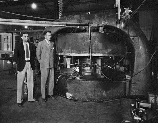
Using this design, Lawrence’s first accelerator, built in 1931, was able to accelerate beams of Hydrogen ions to 80keV. After some modifications to the original design, Lawrence was able to ramp up the energy of the output beam to 1.22MeV (1,220,000eV) and repeat Cockcroft & Walton’s result of nuclear disintegration of Lithium by 1932. The Cyclotron became the accelerator of choice across the world from many years as it was more cost and size effective than other accelerators.
|
Lawrence and Livingston standing beside their 27" Cyclotron. Image credit: Lawrence Berkeley National Laboratory |
The Betatron
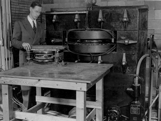
The physical principles governing the Betatron were first described by Widerøe in a 1928 paper and put in to practice in 1940 by Donald Kerst. The development of the Betatron was driven by the demand for high energy X-rays and gamma rays for medical and research use.
The electrons in the chamber maintain a constant radius of orbit (4) whilst being accelerated, due to the centripetal force (7) generated by the particle motion, so long as the magnetic fields satisfy the Betatron principle. Once accelerated, the electrons are directed out of the doughnut chamber, or inwards, towards a metal target (8) to produce X-rays. The first Betatron built by Kerst in 1940 was capable of producing 2.3MeV electrons, but by 1950 he had built a Betatron capable of producing 300MeV electrons.
|
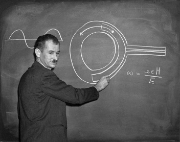
Kerst with his first betatron (table) and his larger 20MeV betatron (behind). Image credit: University of Illinois |
The Microtron
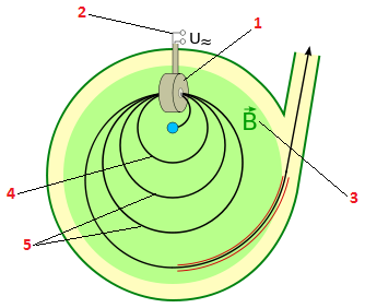
The Microtron is a particle accelerator similar to the Cyclotron. However, the physics governing the design of the Cyclotron is based on classical mechanics (the physical laws describing slow moving objects relative to the speed of light). This placed an upper limit on the energy that particles can be accelerated to of 25MeV, as due to the effects of relativity (as described by Albert Einstein), the mass of particles approaching the speed of light changes. In 1945 Vladimir Veksler invented an accelerator which by taking into account this change in mass could accelerate light particles like electrons beyond this upper limit that became known as a Microtron.
|
|
In a Microtron, electrons are accelerated from rest in an accelerator cavity (1), driven by an AC voltage (2). After leaving the accelerator cavity, the electrons, under the influence of a magnetic field (3), move in a circular path back into the accelerator cavity where they are accelerated again (4). With each pass through the accelerator cavity, the electrons gain more and more energy and therefore, according to Einstein’s famous equation E = mc2, gain mass (as mass is equivalent to energy). The increase in mass results in an increase in the radius of the orbit of the electrons (5).
|
For electrons to continue to be accelerated, they need to be arriving at the accelerator cavity at the same time that the AC voltage is at a peak. This is possible if the electrons, starting from rest, receive an energy increase from the accelerator cavity on each pass, equivalent to their rest energy (E0 = m0c2, rest energy is equivalent to rest mass), and that the increase in the period (the amount of time taken to complete one orbit) of the orbit after each pass through the accelerator cavity is equal to an integer multiple of the period of the AC voltage in the accelerator cavity.
These conditions follow from the algebra in Veksler’s 1944 paper that describe the physical principle known as phase stability (The American physicist Edwin McMillan published the same idea at almost the same time and is often credited with its invention). These conditions can be satisfied by making adjustments to the magnetic field strength and the energy gain from the accelerator cavity.
|
Edwin McMillan explaining the concept of phase stability. Image credit: Lawrence Berkeley National Laboratory |
By taking advantage of phase stability, Microtons were able to accelerate electrons beyond the 25MeV limit. Microtrons are still in operation today and a notable example is the Mainzer Mikrotron (MAMI) in Mainz, capable of accelerating electrons to 855MeV.
The Synchrocyclotron
The Synchrocyclotron is a modification of the classic Cyclotron design developed to overcome the relativistic limitations on the classic Cyclotron as described in the previous section. The Synchrocyclotron differs from the classic Cyclotron in that the frequency of the AC voltage does not remain constant, it synchronises with the orbit frequency of the accelerated particles. Put simply, as the particle energy, and therefore mass, increases, the time it takes for the particle to complete one orbit increases, meaning it arrives at the surface of the electrode, where it is accelerated, less frequently. If the AC voltage also peaks less frequently so as to match the decreased orbit frequency of the particles being accelerated then the particle and voltage avoid dropping out of sync and the particles can be accelerated beyond the relativistic limit of the classical Cyclotron. The first Synchrocyclotron was a modified Cyclotron completed by researchers at Berkeley. They found that much lower voltages were needed to accelerate particles than in a Cyclotron and by 1947 they were able to accelerate Deuteron (an isotope of Hydrogen) ions to 190MeV and He2+ (an isotope of Helium) ions to 380MeV.
|
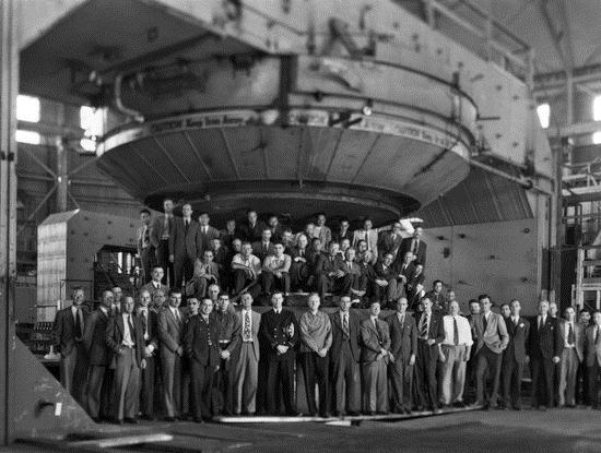
Scientists at Berkeley with the 184" Synchrocyclotron after upgrade. Image credit: Lawrence Berkeley National Laboratory |
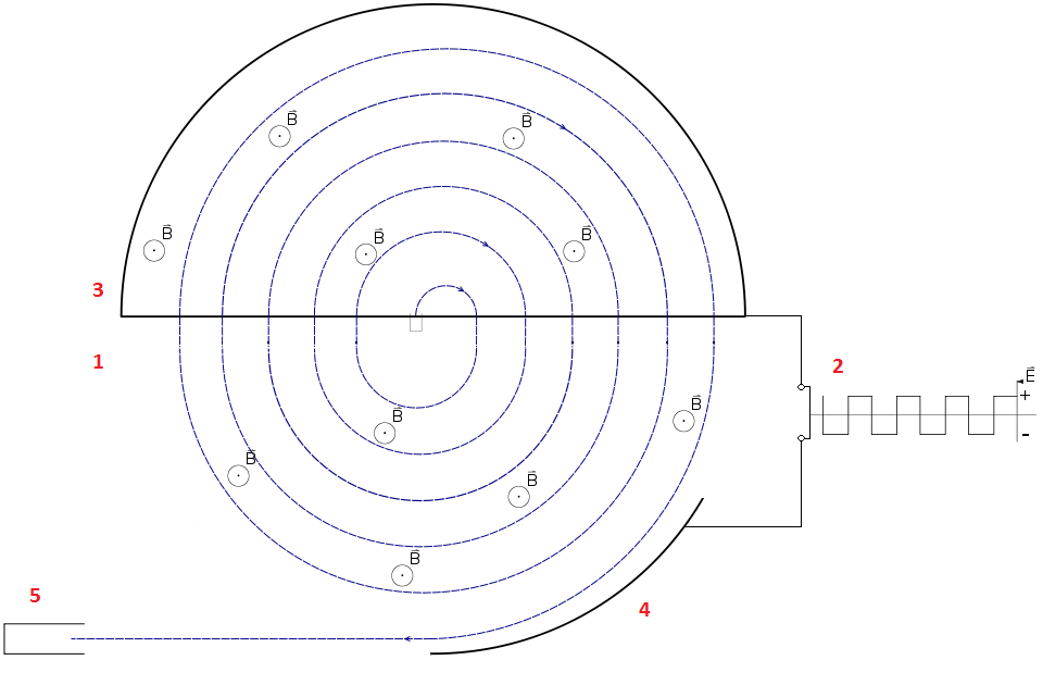
The modified Cyclotron had one of the D-shaped electrodes removed (1). The particle is accelerated in the same way as in a Cyclotron except that the RF generator responsible for producing the AC voltage which accelerates the particle is replaced with a variable frequency RF generator (2) so that the AC frequency can be synchronised with orbital frequency of the particle. The AC voltage is applied across the remaining D-shaped electrode (3) and a new deflecting electrode (4) which is responsible for directing the particle out of the accelerator and towards a target (5).
|
A diagram showing the basic design of a Synchrocyclotron. Image credit: TNorth, Wikipedia, Modified: Daniel Potter/TIARA |
The Synchrotron
The basic principle of the Synchrotron is to maintain the accelerated particles at a constant orbital radius. This is achieved by synchronising the magnetic field strength with the energy of the accelerated particles. So, as the particles are accelerated and gain energy, the magnetic field is increased, keeping the particles orbit constant. The first Synchrotron to be built was a modified Betatron and was completed by two English physicists, Frank Goward and D. Barnes. Many Synchrotrons were built after this and by 1954. Under the leadership of Phillip Dee, a Synchrotron capable of accelerating electrons to 350MeV was built at the University of Glasgow.
|
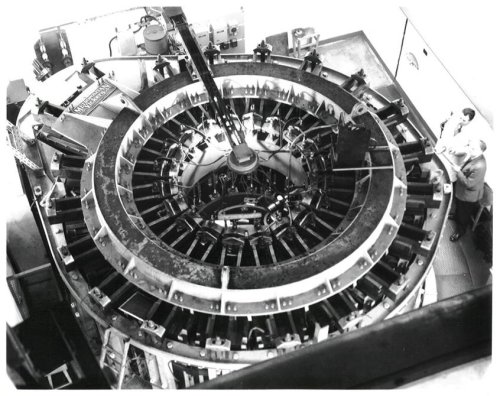
The 350MeV electron Synchrotron at University of Glasgow. Image credit: University of Glasgow |
The upper limit to the speed of any object is the speed of light, nothing can travel faster. Light particles such as electrons begin to approach the speed of light at fairly low energies. Heavier particles like protons approach the speed of light at much higher energies (a proton is almost 2000 times heavier), so to produce higher energy beams, scientists looked to accelerate protons rather than electrons. Due to the larger mass of protons, accelerating protons in a Synchrotron is slightly more complicated than accelerating electrons. As the protons are accelerated, their orbital frequency increases, meaning that the frequency of the AC Voltage across the accelerator gaps also has to increase. However, the strength of the magnetic field also has to increase to maintain a constant orbital radius, so the orbital frequency of the protons, the frequency of the AC voltage and the increase in magnetic field all have to be synchronised. The first proton Synchrotron to be completed was the ‘Cosmotron’ at Brookhaven, finished in 1952 and by 1954 it was accelerating protons to 3GeV (3,000,000,000eV).
In 1947 whilst working on their electron Synchrotron, scientists working at General Electric’s Research Labs observed for the first time what became known as synchrotron radiation. Synchrotron radiation is an electromagnetic radiation, usually in the X-ray range, emitted by charged particles traveling at relativistic speeds, forced to take a curved path by a magnetic field. At first synchrotron radiation was seen as an inconvenience as it caused a loss in energy for the accelerated particles, however it wasn’t long until its usefulness in spectroscopy and crystallography was realised and today Synchrotrons are built for the sole purpose of generating synchrotron radiation.
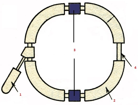
The development of the Synchrotron led to the construction of large scale accelerators, as in a Synchrotron the components can be divided in different sections. The acceleration of the particles and the bending of the particle’s path can be split meaning that the accelerator, as opposed to being circular, can be slightly oval shaped (like a NASCAR race track), or like a square with rounded corners. A particle in a Synchrotron will be accelerated in accelerator gaps whilst traveling along the straight section, as they would be in a Linac. The particle’s path is then curved by a magnetic field, taking the particle to another straight section where it is again accelerated. The particle will go round and round the accelerator, gaining more and more energy with every revolution. Below is a diagram of a simple proton Synchrotron.
First protons are accelerated in a pre-accelerator, which could be a Cockcroft-Walton or Van de Graaff accelerator, a Linac, or in the case of some larger Synchrotrons like the SPS at CERN even a smaller Synchrotron.
|
|
The protons then enter the Synchrotron via an injector (1). The protons are then made to follow a curved path by bending magnets (2), which can be either electromagnets or superconducting electromagnets. After leaving the bending magnets the protons travel to an accelerating cavity (3) where they are further accelerated. The particles are again made to follow a curved path bringing them to a second straight section where they can either be accelerated again in another accelerator cavity, or in the case of the example below, simply follow a straight path (4) before being directed again to another bending magnet which will direct the protons to the second accelerator cavity (3) parallel to the first. |
The synchrotron is an extremely important type of accelerator which is used today to accelerate electrons, protons and atomic nuclei, in many cutting edge research facilities world-wide.
The Storage Ring Collider
The idea for colliding beams of particles is credited to Widerøe, who talked of the idea, purely conceptually at the time, of colliding two beams of particles rather than firing a beam of particles at a stationary target as early as 1943. It wasn’t until 1954 that Kerst independently developed Widerøe’s idea that the potential of this idea was realised by the scientific community, and the idea for the storage ring collider was conceived. The first storage ring was built in 1960 by Bruno Touschek in Frascati and named Anelli di Accumulazione (AdA) but it was too small to be of much use for research. Today the most famous storage ring collider is the Large Hadron Collider (LHC) at CERN, at a diameter of 27km and spanning two countries. It is the biggest experiment ever undertaken in science. The LHC primarily collides beams of protons and has so far collided beams of protons with energies of 3.5TeV (3,500,000,000,000eV) resulting in a 7TeV collision. The LHC is designed so that it can also accelerate heavy ions like Lead to up to 575TeV to try and replicate the conditions in the early universe, immediately after the big bang.
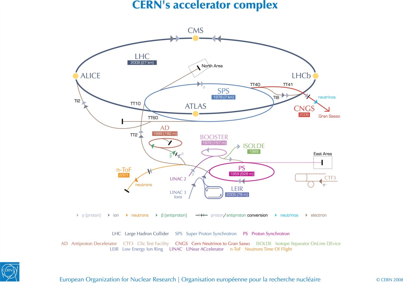
Before reaching the Collider Ring at the LHC, particles are first sent through a chain of particle accelerators. Protons are first accelerated to 50MeV by a Linac (LINAC 2), before being sent to a Synchrotron called the Proton Synchrotron Booster (PSB) and then the Proton Synchrotron (PS) itself, where the protons are further accelerated to 1.4GeV. The next stop for the protons is the Super Proton Synchrotron (SPS), where they are taken from 1.4GeV up to 450GeV, the protons are then injected into the main ring (LHC) where they eventually reach their final energy of 7TeV and are collided. The beams of charged particles travel down two separate accelerator tubes in opposite directions. The beams can meet in four locations on the circumference of the 27 km diameter ring, where giant detectors are placed to study the collisions (CMS, ALICE, ATLAS and LHCb).
A diagram of all the accelerators at CERN. Image credit: CERN
